
Successful operation of a nitrous truck hinges on a thorough understanding of its service power requirements. From industry manufacturers to small business owners in construction and heavy industries, knowing how to properly power up a nitrous truck is crucial for ensuring safety and efficiency during operations. This article will delve into five chapters, starting with an examination of nitrous truck service power requirements, key components involved in powering up the service, and essential safety considerations. Following these foundational insights, troubleshooting common issues will be covered, ending with best practices for maintenance of nitrous truck service power systems. By exploring each chapter, readers will gain a holistic understanding of how to effectively manage service power in nitrous trucks.
Orchestrating Service Power for a Nitrous-Enhanced Truck: Safety, Systems, and Real-World Tuning
Powering up a service system on a nitrous-enhanced truck is less about pushing a switch and more about harmonizing an intricate web of electrical architecture, mechanical capability, and disciplined procedures. The goal is not only to achieve the desired surge of power but to do so without compromising the engine’s longevity or the safety of the operators. In this light, any discussion about powering up the service system must begin with respect for the manufacturer’s service manual and the embedded interlocks designed to prevent missteps. A responsible approach treats the service power as a carefully choreographed sequence, where checks, protections, and diagnostics form the backbone of every operation. The surrounding reality of heavy-duty trucking—where engines endure long hours and varying workloads—only intensifies the need for a robust power strategy. The same careful consideration applies whether the vehicle is used for drag-inspired performance, heavy towing, or routine road duty. The critical issue is to align the electrical and mechanical systems with the intended duty cycle, ensuring the truck can reliably deliver the requested performance without inviting undue stress on pistons, rods, or bearings. The engine’s current condition, compression ratio, fuel delivery, cooling capacity, and the chosen use case all factor into how the service power should be prepared and managed. When the intent is to maximize response while protecting engine integrity, there is a clear logic to the power equation: more power must be earned through balanced upgrades, precise tuning, and vigilant monitoring rather than through aggressive overshoot that can invite detonation or component fatigue. The ambient environment becomes part of that equation too, because air and air-fuel mix behavior shift with temperature, humidity, and altitude. Understanding this interplay helps avoid lean conditions when the system is engaged under less-than-ideal weather or during rapidly changing conditions. In practice, operators should think of the service power as a dynamic resource, not a fixed setting. The system’s ability to deliver consistent performance depends on the integrity of the vehicle’s electrical backbone—the battery health, the alternator’s capacity, wiring harnesses, and protective circuitry. A well-conditioned electrical system reduces voltage sag that can upset sensors, ecu logic, and spray control solenoids. It also supports the ancillary systems that keep the truck safe while the nitrous injection is active, such as cooling fans, intercoolers, and intake air management devices that can modulate temperature and density of the charge. The numbers that define this balance are rarely universal. They hinge on the specific engine build, the cooling capacity, and how the vehicle will be used. A shop that routinely tunes for competitive performance will begin with a thorough assessment: compression health, ring seal, and cylinder head condition; the fuel delivery system’s capacity and injector responsiveness; and the cooling system’s ability to shed the heat generated during high-oxygen operation. Only after a clear picture emerges can a responsible power plan be drafted. One of the more subtle factors is ambient temperature, a variable that has a marked effect on nitrous delivery and combustion stability. Manufacturers generally emphasize operating ranges where the density of the nitrous charge is optimized for stable oxygen delivery and predictable combustion. Within the roughly recommended band, around moderate temperatures, the risk of lean misfire is minimized, and the power curve tends to be more reliable. Departures from that range can introduce fluctuations in nitrous flow, which in turn shifts air-fuel balance and ignition timing. The consequence can be detonation or pre-ignition if the fueling and timing aren’t adjusted accordingly. Even such seemingly mundane details as intake air temps and cooling capacity gain outsized importance when a vehicle is under load and the nitrous system is demanding more air per cycle. Because the service power is intimately tied to the engine’s ability to manage heat, any power plan should integrate a robust cooling strategy and a data-logging framework that flags abnormal temperature rises or unexpected pressure swings. In the day-to-day operation of a nitrous-enabled truck, reliability comes from a disciplined maintenance culture. This is where the story of service power becomes a lens on broader fleet practice. The trucking world continues to move toward more systematic maintenance regimes, particularly in private fleets that rely on predictable uptime and steady performance. The trend toward proactive inspection of electrical harnesses, connectors, and fuse blocks mirrors the emphasis on engine health and cooling capacity. Operators who pair a conservative, data-backed approach to power with meticulous upkeep are the ones who translate potential performance into consistent, repeatable results. For those who want to place this stance into a real-world frame, consider how maintenance trends in private fleets emphasize inspection intervals, corrosion prevention on exposed connections, and the alignment of service dollars with reliability goals. That mindset—of treating power as a managed resource and coupling it with disciplined upkeep—translates well into the nitrous domain. It is not enough to dial in a higher boost; the system must be supported by electrical resilience, robust interlocks, and verified sensor feedback that confirms safe operation across the full range of temperatures and loads. The engineering challenge is thus not simply about delivering more oxygen but about delivering it with a sustained, interpretable signal to the engine control system, while the vehicle’s electrical architecture remains within safe operating envelopes. In practice, this means a cautious, data-driven approach to any increase in power: verify battery and alternator health, confirm wiring integrity, ensure sensors are within calibration, and confirm that the cooling system can absorb the added heat load. The discussion also touches on the role of the service script and the control logic that governs the nitrous delivery. If the power plan relies on electronic controls to meter the flow, the software must be tuned to respond predictably to throttle input and transmission load. In many respects, this is where the art meets the science: you are balancing the desire for immediate performance with the need for ongoing durability, and you are doing it within a framework of validated procedures, interlocks, and diagnostic capabilities. To anchor this approach to everyday realities, consider how the industry values a predictable, well-documented maintenance cadence. Even small fleets that emphasize routine maintenance pay dividends in uptime and wear reduction, reinforcing the view that power and service capability are only as good as the system that sustains them. The community of operators who share notes on maintenance, tuning, and reliability generally agrees on a few core ideas: never push beyond the engine’s proven limits, never skip safety interlocks, and never neglect cooling and fuel-management systems when the nitrous load increases. And while the specifics of a given truck’s build will shape the exact numbers, the underlying discipline remains constant: ensure power is earned, not imposed, through careful assessment, validated upgrades, and continuous monitoring. For a broader view of how practices like these translate into operational realities, see the discussion around trucking maintenance trends in private fleets. It highlights how fleet managers are prioritizing reliability, predictive maintenance, and data-driven tuning—a philosophy that naturally extends to the management of service power in nitrous-enabled applications. In short, powering up the service system is not a one-time adjustment but a living process. It requires a clear understanding of how electrical, mechanical, and thermal subsystems interact under peak demand, a commitment to safety interlocks and diagnostics, and a deliberate cadence of inspection and tuning that respects the engine’s durability. As teams gain experience, they build a practical intuition for balancing ambition with prudence, ensuring that every performance gain comes with a commensurate foundation of safety, reliability, and long-term operability. For readers seeking a grounded, technical reference that complements this discussion, the official technical-support resources for nitrous-oxide systems provide authoritative guidance on power requirements and safe tuning practices. External resource: https://www.nos.com/support/technical-support
Power-Up Protocols for Nitrous-Enhanced Service Trucks: Precision, Protection, and Performance
Powering up a nitrous-powered service truck demands more than simply flipping a switch. It requires a deliberate sequence, clean supplies, and a calibrated mind for risk and reward. In the workshop and on the road, the service system must respond the moment it is asked, yet it must do so within bounds that protect the engine, the drivetrain, and the crew. The most reliable guidance comes from the official service documentation produced by the system’s manufacturer, which details the correct power-up sequence, safety interlocks, and diagnostic checks. In this chapter, we synthesize those principles into a practical narrative focused on three core components that determine how well the service system wakes up: filtration, the horsepower increment, and the calibration architecture. Each piece plays a distinct role in ensuring that the act of increasing nitrous flow translates into predictable throttle response, controlled pressure, and durable operation. The aim is not to maximize momentary power alone, but to sustain reliable performance under load, in varying temperatures, and under the stresses of real-world service cycles.
First, filtration. Nitrous and fuel lines carry fluids that can harbor microscopic contaminants, which can wreak havoc on solenoids, jets, seals, and sensors. A clean feed is the bedrock of consistent performance. Start with confirming the nitrous and fuel filters are of the correct rating and free from past service reasons to replace. Inspect the housings for cracks and ensure O-rings are intact. During the power-up, verify that the filters are seated correctly and that there are no cross-leaks or bypasses in the lines. If a filter shows any sign of distress, replace it before energizing the system. Debris in the flow path can immediately skew pressures, causing the controller to over or under-supply nitrous during the initial ramp. This would manifest as a rough start, hesitation, or spurious pressure spikes that can harm valves or the engine. In practice, teams often pair a filter check with a quick gauge verification, looking for stable base pressures before enabling the system. The emphasis is on establishing a pristine, stable baseline so that the first trigger push benefits from clean delivery rather than from a sudden correction made after a fault has already occurred. Beyond the filter itself, pay attention to hose integrity and the connectors that feed the rails. Tiny leaks or micro-fractures in connectors can silently erode performance and safety margins when the system moves into high-flow conditions. Routine, disciplined filtration checks set the stage for the rest of the power-up and create a clear, auditable trail for maintenance records.
Second, the appropriate horsepower increase. The instinct to push more power is strong, but the smart approach starts with understanding the engine’s tolerance, the drivetrain’s ability to handle extra torque, and the cooling system’s capacity to absorb heat. The goal is to tailor the nitrous augmentation to the specific application: a service truck that may perform under heavy load on a highway grade or in urban idling cycles will have different demands than a race-focused installation. The chosen increment should respect the engine’s RPM envelope, the size of the fuel system, and the reliability margins built into the calibration. Too much nitrous relative to fuel can cause a lean condition, excessive cylinder pressure, and valve train stress. Too little may yield an unsatisfactory return on the investment. In practice, engineers and technicians map a safe range of horsepower increases, often validating it with dyno tests and on-road data while monitoring air-fuel ratio, cylinder pressure, and exhaust temperatures. The objective is a predictable, linear response: as you lean into the throttle, the system delivers more nitrous, the fuel system adds fuel in step, and the engine breathes with controlled lean zones that do not shock the internals. In the service context, this balance translates into smoother power delivery during gear changes, steadier pull on hills, and a more controllable idle when the high-demand cycles are paused. It is a reminder that a well-chosen horsepower target is a negotiation: you trade some margin for reliability, and you gain steadiness for the long haul by protecting components that carry the heaviest load. The practical upshot is a shift from chasing peak numbers to cultivating repeatable performance under the conditions a service fleet experiences daily—hot days, cold starts, and the occasional heavy-duty surge as vehicles move more material per shift.
Third, calibration and system design. This is where the blueprint becomes a practical, safe operating plan. A robust system design includes not only the physical layout and line routing but also the control logic that governs when, how quickly, and by how much nitrous is introduced. Calibration must account for ambient temperature, fuel quality, sensor latency, and the tolerances of the injectors and solenoids. The objective is to align the mechanical flow with the electronic commands, and to do so with a margin that prevents mechanical fault under peak demand. A careful sequence starts with powering up the controller and verifying that all interlocks engage correctly. After that, technicians should observe baseline pressure readings, verify that the nitrous and fuel rails reach their expected setpoints, and confirm that the throttle and nitrous mapping respond smoothly to input without any oscillations or overshoot. Where possible, a dynamometer-based calibration yields a repeatable reference, but in-service trucks, a road test with data logging is often the practical complement. The calibration should also include safeguards: checks for leaks, clamps that hold hoses securely, safe routing to prevent chafing, and protective sheathing to guard against heat soak. The aim is to create a coherent system where every parameter—pressure, flow, ignition timing, and fuel trim—works in harmony rather than against one another. In this sense, calibration is not simply a tuning exercise; it is a design discipline that embeds safety into the power-up sequence, ensuring that the moment the operator activates the nitrous system, the engine mapping, fuel delivery, and sensor feedback move in lockstep toward a controlled, repeatable response. A thoughtful design also anticipates service realities: simple field diagnostics, robust fasteners, and accessible service ports that allow quick checks without disassembly. These considerations reduce downtime and improve the reliability of service operations, making a deliberate, well-documented design the backbone of every successful activation.
Beyond the hardware, the human factors matter. Operators must follow the documented power-up sequence in the service manual and respect interlocks that prevent inadvertent activation. Good practice includes inspecting for fuel leaks, securing all covers, and confirming that the service system is stable before pressurizing. When possible, perform the initial test in a controlled environment with a visible gauge and a remote stop mechanism available. The safety margin remains the priority: if the numbers drift outside baseline, the system should be shut down and inspected rather than pushed to continue. This slows the thrill of more power, but it protects the engine and the crew, which is the true measure of professional reliability in service operations. The guidance you follow will also link you to manufacturer documentation and official technical support resources that provide the exact sequence for your specific hardware. While the principles described here apply broadly, the precise steps, interlocks, and diagnostic checks are defined by the equipment’s official manual. For practitioners who want to extend their knowledge, the official technical support resources offer detailed, model-specific instructions and troubleshooting steps that complement the general framework described here.
Finally, as you build confidence, remember that the most trustworthy information lives with the system’s developers. When in doubt, consult the official technical support resources, which document the safe, recommended practices for installation, power-up sequencing, and ongoing maintenance. This is not a place for improvised procedures, but for a disciplined process that ensures longevity and safety during every service cycle. For broader fleet context on maintenance strategy, many fleets turn to industry-wide trends in private truck maintenance, which you can explore here: Private Fleets Maintenance Trends. For deeper technical guidance, consult the official support portal to access model-specific power-up sequences and diagnostics: https://www.nitrousoxidesystems.com/support
Ignition-Safe Startup: A Practical, Safety-First Guide to Powering Up the Nitrous Service System on a High-Performance Truck

Powering up the nitrous service system requires discipline and a methodical procedure. The aim is to create a safe, controlled environment, confirm depressurization, and reintroduce pressure only through steps aligned with manufacturer guidelines. When followed carefully, the startup becomes a rhythm of checks and communication that preserves the integrity of the powertrain, the nitrous system, and the people nearby.
Environment first: nitrous oxide is an oxidizer; work in a well ventilated space, outdoors or in a workshop with exhaust and fresh air. No smoking, no open flames, no sparks near components, and use non sparking tools when handling the system.
PPE: safety glasses, gloves, long sleeves, flame resistant outerwear as needed. Frostbite risk from cold gas; inspect for frost on valves and lines.
Depressurization: confirm complete depressurization of bottle, lines, solenoids before any tool touches fittings. This resets the system and reduces risk of accidental activation.
Bottle handling: treat bottle with respect, store upright and secured; do not use damaged bottles.
Electrical safety: disconnect and isolate power to control circuits before service; remove power from battery, verify no residual voltage before disassembly.
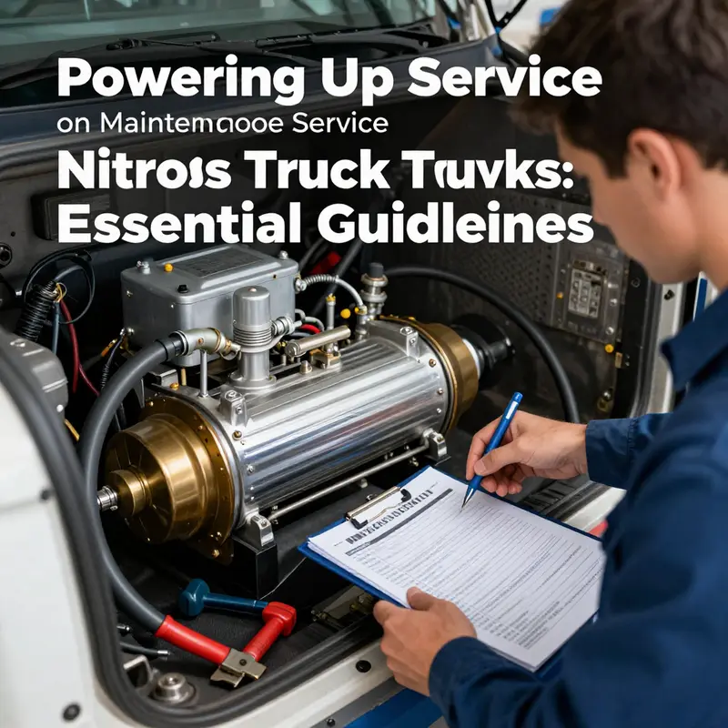
Training and procedures: only trained personnel; follow manufacturer procedures; treat manuals as living documents; document deviations.
Startup sequence: after depressurization, reconfirm no ignition sources and secured electrical connections; inspect lines and fittings for wear or leaks; reassemble and re-pressurize gradually; perform a low rate leak test with approved methods; keep flames and sparks away.
Re-pressurization: monitor interlocks, gauges, temperatures; halt on anomalies and return to depressurized state.
Maintenance context: link to broader maintenance practices; record service logs; refer to NFPA 800 for fire protection in racing environments; provide external link.
Note: Always defer to official service manuals for equipment specific steps; ensure traceability and auditable safety.
Powering the Service Heartbeat: Safe, Sequential Activation for Nitrous-Driven Trucks
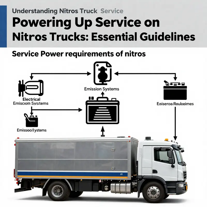
Powering up the service system on a nitrous truck is not a moment to improvise. It is the moment when safety, reliability, and performance hinge on a disciplined sequence described in the manufacturer’s documentation. The service system comprises more than a dozen electrical and electronic components: a main power distribution network, a couple of control modules, sensor arrays, warning interfaces, and interlocks that guard the pressurized nitrous and fuel circuits. In a nitrous-equipped vehicle, this choreography becomes even more critical because misalignment or a skipped step can ripple through fuel delivery, nitrous flow, and emission controls, potentially triggering alarms, reducing performance, or compromising safety. The message is clear: a careful power-up is a foundational act that governs what follows on the road or in the test cell.
Because there is no universal protocol in the general literature, technicians rely on the official service manual. The first principle is simple: power up is a controlled process, not a single switch flip. The chapters in the manual describe a safe sequence that starts with the battery and grounding, proceeds through the central power management module, and ends with the verification of all subsystems, including the nitrous control valves, the fuel pump, sensors, and the engine control unit. The aim is to bring every module online with a known state, so that diagnostics can read accurate data rather than random fault codes from a partially energized network. This approach protects both the technician and the vehicle while laying a transparent baseline for future service.
Preparation is more than a checklist. It is about environment, timing, and intent. Before touching a single cable, the workspace must be clear of tools and personnel. PPE is worn, and ventilation is considered because some nitrous systems operate with pressurized volumes that can cause harm if a leak or misfire occurs. The service bay must be dry and well-lit, and the power management scheme described in the manual may dictate that the main power switch remains in the OFF position until all harnesses are verified. Once the technician confirms the harness grounds are clean and secure, the power-up can begin. The battery’s state of health is assessed, not just its voltage. A healthy battery shows consistent current delivery under load; aged or degraded cells can droop during a boot, causing intermittent faults that ghost into the control software. A careful eye is kept on corrosion at grounds, the integrity of fasteners, and the condition of protective sleeves along high-current runs. These details matter because robust grounding and clean connectors reduce the risk of sparks or misreads that can cascade into failed diagnostics.
The actual sequence begins with establishing the primary power bus. The central power management unit is energised first, and it performs a self-test of the electrical infrastructure—the wiring harness, fuses, and relays associated with the service network. If the bus is stable, the engine control unit initiates its boot sequence, negotiating with the nitrous control module and the fuel system controller. The handshake is a silent conversation: modules check their firmware versions, corroborate sensor availability, and confirm that the interlocks are ready. If any module reports a fault, the system stops the power-up, logs the fault, and presents a clear readout on the service interface. This is where the manual’s caution becomes real. The moment a fault appears, the operator must document it and follow the recommended containment procedure, rather than continuing to force power through a fault path. The point is not to rush ahead but to secure a verifiable state where every component can be trusted to report accurately during operation.
Once the microprocessors are confident in the baseline state, the nitrous management system steps into standby. The risk-reducing steps are not about rushing to full pressure but about validating readiness. The nitrous bottle and lines must already be verified for secure connections and leak checks. The service power-up does not energize nitrous solenoids to open flow; it enables a safe, low-energy standby. The fuel pump is primed, and the low-pressure and high-pressure sensors are polled. The diagnostics routines sweep through all the injection ports, the valve trains, the flow meters, and the ignition timing controller. Any deviation triggers a fault lockout, and the system refuses to leave standby until the problem is cleared. This staged awakening is not about maximizing pressure during boot; it is about ensuring the control logic can measure, verify, and hold the system in a safe state while the operator confirms that the mechanical side is intact. The discipline mirrors broader maintenance philosophy: you prove readiness before you demand performance.
With the system reporting no faults, the final step is a guarded transition to active service. Operators watch the readouts for pressure stability, temperature ranges, and alert flags. The nitrous solenoids move from their safe, closed position to a known, controlled state only after the service interface confirms a safe sequence. The engine control unit then assumes full control, coordinating fuel delivery, ignition, and nitrous flow in a synchronized fashion. The result is a system that is predictable and auditable, a feature not only of reliability but of safety. The manual emphasizes logging every power-up: the time, the technician, the module statuses, the fault history, and any anomalies observed during the boot. This log becomes a reference for maintenance and a baseline should future service events require troubleshooting. Some fleets integrate these logs into broader maintenance dashboards, aligning with evolving private fleets trends in trucking maintenance. private fleets trends in trucking maintenance. This is a quiet reminder that the way we manage and record power-up events contributes to overall vehicle uptime and safety. For broader context on how service practices are evolving across fleets, consider the industry-wide conversations about maintenance standards and the role of structured checks in reducing downtime. This chapter should be read with the idea that every power-up is a test of discipline as much as a test of hardware.
As you move through power-up with the official manual in hand, you cultivate a discipline that serves not only performance but compliance. In nitrous-equipped trucks, safety interlocks sit between energy and motion. They monitor bottle pressure, line integrity, and the integrity of the ground path. They prevent inadvertent nitrous release or fuel misdelivery while the vehicle is in the diagnostic state. If an interlock is tripped during boot, the sequence halts and prompts the operator to address the condition. This is the moment to re-test the environment, reseat connections, and re-run the self-diagnostic loop. The goal is to reach a state where the service system can operate in a controlled, auditable fashion, allowing the truck to perform on the road or in a test cell without surprises. The best practice is to treat the power-up as a procedure that earns you confidence in the entire propulsion and delivery chain.
In the end, the power-up ritual is not a one-off act but a preventive habit that threads through maintenance philosophy. It links the mechanical health of the nitrous plumbing, the electrical health of the bus, and the software health of the control algorithms. When done correctly, the service system awakens without fault, the data streams illuminate, and the operator can proceed with confidence. When done incorrectly, the consequences cascade from the dashboard to the chassis, and the fault alarms are not mere noise but a clear signal that something essential did not wake up correctly. Across fleets that rely on performance modifications, this disciplined approach to power-up becomes part of the daily routine, a foundation on which the rest of the operation rests. As you move into the next chapter, you will see how this careful attention to electrical and control health supports not just peak performance but long-term reliability in diverse operating environments.
null
null
Final thoughts
Understanding how to power up service on a nitrous truck involves grasping the critical components, safety practices, and maintenance routines. Each chapter elucidates key insights into this complex process, ensuring that both industry professionals and small business owners are well-equipped to handle the challenges of powering up these specialized vehicles. The information covered emphasizes the importance of thorough preparation and adherence to safety protocols, ultimately fostering more efficient and safer operations within the nitrous truck sector.